|
Instructions written July 2000.
This Mov'it/Porsche brake kit has been discontinued, but instructions remain available to assist current owners and anyone else interested in fabricating their own system. Various other options, now available from StopTech and Brembo, are significantly easier to install.
Much of the difficulty associated with the installation of this Mov'it rear brake kit has to do with the small rotor size (322mm) resulting in the positioning of the Porsche caliper very close to the hub. This requires grinding of mounting ears, lower control arm, and knuckle as well as modification of the parking brake mechanism.
Brembo and StopTech rear brake kits for the E39 use larger rear rotors and require no grinding of control arms. Installation is only slightly more complicated than changing pads and rotors and can be done by a reasonably skilled person in about two or three hours. Don't let these complicated Mov'it brake kit installation instructions intimidate you. StopTech and Brembo brake kit installation is much easier.
|
|

|
The Mov'it rear brake kit for the E39 is one of the more challenging to install. This is not for beginners. Plan on an entire weekend to install both sides.
To retain the parking brake function inside the rear rotor, some part swapping and machining is done by Mov'it. The BMW E39 parking brake shoes are too big to fit inside the 322mm Porsche 993 TT rear rotors, so the smaller BMW E38 750iL parking brakes are supplied.
|
|
Safety Warning:
Working on your own car can be dangerous. Even quality jack stands can collapse if not positioned properly, and a floor jack can fail suddenly and without warning. You can be seriously injured or even killed if you do not follow proper safety procedures. Please use a floor jack and quality jack stands to support your car so a failure of any single support is less likely to result in a car falling on you! Zeckhausen Racing LLC assumes no liability, expressed or implied, for the improper installation or use of these components.
|
|
Installation Instructions

|
Chock front wheels to keep the car from rolling.
Position a floor jack under the differential and raise the back end, then lower onto a pair of jack stands, positioned at the plastic jacking points along the bottom of the frame rails.
Allow most of the weight to rest on the stands, but leave the floor jack in place as a safety backup.
|
|
|
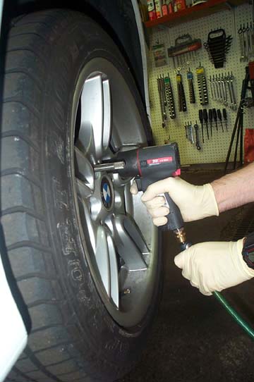
Use a 17mm socket to remove rear wheels.
A quality air wrench makes the job go faster. I use a compact Ingersoll-Rand Model 2121 Heavy Duty Series. The small size allows it to be used in places a typical air wrench won't fit.
|
|
|
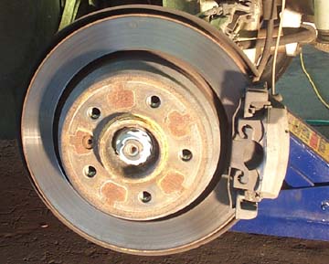
Stock 540i rear brake shown.
Note the backing plate that extends from behind the rotor. In a later step, we'll be trimming the plate to make room for the larger rotor and calipers.
|
|

|
BMW uses a sensor to monitor the condition of the passenger-side, inboard pad. When the pad is worn, a wire embedded in the plastic tip of the sensor is cut by the rotor and a warning appears on the dash. The Mov'it kit requires us to disable this function.
StopTech rear brake kits do not require these steps, since the pad wear sensor function is retained.
|
|
|
Pull the sensor wire from the brake pad with your fingers. If it doesn't pull straight out, rock it from side to side while pulling.
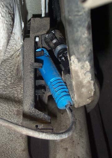
Follow the sensor wire back behind the inner fender liner to where it enters a small plastic holder. Both brake pad wear sensor and ABS sensor harnesses terminate here. Disconnect the brake pad wear sensor connector by squeezing the retaining tabs on the male end and pulling it straight out.
The photo shows the wear sensor harness removed, while the male end of the plug remains behind.
The blue cylinder to the left is the ABS sensor harness connector and may be ignored.
|
|

|
Cut the pad wear sensor off the harness, strip the insulation off the end of the wires and twist the ends together. Solder and cover with electrical tape.
Reattach connector to the base, making sure the pins line up.
Turn ignition key to run and verify no warning messages about brake pads. A warning means you didn't properly re-connect the harness. Pull it apart, check alignment, then reconnect.
To reset the warning, turn key to run position, but do not start car. After 45 seconds, the warning light should reset.
|
|

|
Remove the spring steel clip from the caliper.
Eye protection is suggested here.
Squeeze the spring clip with needle nose pliers or compress it with a small pry bar. Then pull clip forward, away from the rotor. It should pop right off. Try not to bend it.
|
|

|
Remove rear caliper from the caliper carrier (bracket) by using a 7mm Allen bit to unscrew the two slide pins. The slide pins are hidden beneath plastic caps which may be pried off with your fingers. In order to get clearance for your ratchet, while removing the lower caliper slide pin, you may need to jack the suspension up slightly.
|
|

|
Wiggle the caliper until it pulls off the rotor. The outer pad will remain behind on the carrier, while the inner pad will stay clipped to the caliper. Don't force anything. It should come off after a bit of wiggling.
Normally, it is not a good idea to dangle a caliper by the brake line. But in this case, the brake line fitting screws straight into the lightweight caliper. It is fine to let it hang. You won't damage anything.
|
|

|
Use a 16mm socket to remove the two bolts holding the caliper carier to the control arm.
The lower bolt will be partially obstructed by the aluminum control arm. It helps if you use a floor jack to raise the suspension to it's highest point, so the control arm is nearly parallel to the floor. This gives you better access to that lower bolt.
Be careful not to lift the car off the jack stands.
|
|

|
Use a 6mm Allen bit to remove the rotor retaining screw. Save this screw, as you will reuse it later.
|
|

|
Check that the parking brake is not engaged.
Make sure the wheel installation guide tool is still attached so the rotor doesn't fall off and land on your foot. Alternatively, screw a wheel bolt into the hub a couple of turns.
Use a dead blow hammer and strike the rotor until it comes loose. You may need to hit it hard and often if your car is older.
If it still does not come off, go back and check to make sure the parking brake is really disengaged.
|
|

|
This is the parking brake assembly. Study it closely so you understand how it functions and how the parts go back together.
At this point, you may want to take a sharp object and use it to scribe a line in the backing plate, around the parking brake shoes. This will give you an approximate idea of where to cut the backing plate in a later step.
|
|

|
Remove the upper and lower parking brake return springs.
You will need brake spring pliers to remove and reinstall the two springs in the parking brake assembly. The task is made much easier with this tool.
|
|
|
A special BMW parking brake tool is used for removing and installing brake shoe retainer pins.
Use the tool to press down on the retaining pin, then twist 1/4 turn in either direction. It should pop out and the brake shoe will fall into your hand.
|
|

|
This photo should help you understand the proper orientation of all the parts.
The two springs are not the same size. The larger one goes on top.
The cylinder on the bottom, with raised teeth, is an adjustment device which is rotated to make it wider or narrower. This is how you adjust the parking brake.
|
|

|
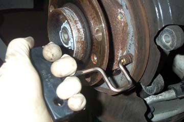
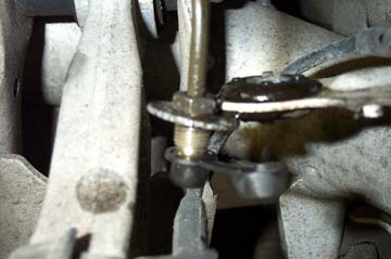
Using a 16mm offset wrench, remove the two bolts shown and pull out the upper support. Remove the rubber gasket.
Note the orientation of the gasket. The depression faces out, as shown. It won't fit properly if you try to install it backwards in a later step.
The tip of the parking brake cable is visible just to the right of the wrench. Push the cable back into the hole so it is out of the way for the next step.
|
|

|
The upper support you just removed will be replaced with a new one that mov'it has machined to fit within the Porsche rotor hat. The old piece is shown on the left. The new one is on the right. (Don't install this yet.)
|
|

|
This shows a summary of the next phase of the installation.
Remember: none of this grinding is required for StopTech or Brembo kits.
We will trim the metal backing plate with tin snips, then remove a small amount of material from the aluminum knuckle and control arm to provide clearance for the caliper, rotor, and adapter bracket. And finally, we'll grind flat the caliper mounting ears so they fit flush with the new caliper adapter bracket.
|
|

|
Remove four 10mm bolts holding the backing plate to the knuckle. Pull backing plate forward and rotate so you may easily cut it with tin snips. The object is to remove enough material so the backing plate can fit inside the rotor, but not too much that the parking brake shoes are unsupported. Cut the plate where it starts to bend, slightly inside the score mark you made earlier. Remember, the E38 750iL parking brakes you will install are SMALLER than the E39 540i parking brakes you removed.
Photo shows the material removed from the backing plate. This piece may be discarded.
|
|

|
Reattach backing plate with four 10mm bolts. Install modified support bracket with two 16mm bolts. Reinstall rubber gasket.
Test fit rotor over hub. If there is no interference, you're set. If scraping is heard, when rotor is turned, you need to determine where to remove material.
Apply tape around the edges of the backing plate, reinstall rotor and rotate. The tape will show wear marks where there is interference. Remove more material and repeat until rotor no longer scrapes.
|
|

|
For the next few steps, you'll need an angle grinder such as the 4 1/2" Sears model shown. It will be used to remove material from the control arm and knuckle.
|
|

|
The grinder is used to remove material from the locations indicated by the red arrows.
|
|

|
Compress the suspension with a floor jack, but stop raising it BEFORE the car lifts off the jack stands..
Install the bracket temporarily on the mounting ears. It will be immediately obvious the control arm interferes with the bracket, especially when the suspension is lowered. Use a marking pen to mark the control arm, then remove the bracket. Grind enough material from the control arm so the bracket clears.
Lower the jack and ensure the bracket clears the control arm, even when suspension is fully lowered.
Caution: Before grinding the control arm, install the protection hose clamp, as described in the next two steps.
|
|

|
Right next to the part of the control arm you are about to grind is a rubber boot. It is easy to damage this boot with the angle grinder. You don't want to do this, since taking that part of the suspension apart to install a replacement boot is not easy.
So how do we protect the boot?
|
|

|
I just happened to have hose clamps on the shelf that were the right size. Open the clamp entirely and thread the metal band around the rubber boot. Then tighten the clamp so the boot is compressed out of the way and completely shielded from any grinder accidents.
Now you can grind to your heart's content.
|
|

|
Grind off the mounting ears so they are just below the level of the caliper mounting surface on the bracket. Place the bracket on the ears to check your progress. You can't put material back, so be patient and remove a small amount at a time.
Now you are ready to attach the caliper bracket. Two different thickness shims were included in the kit to move the bracket slightly inboard, toward the car. Use the thicker shims, placing one between each aluminum ear and the bracket before installing the nuts.
(Note: the shims will protrude above the bracket. Use a file to flatten one edge of the shims so they are flush with the bracket.)
You just installed the following parts in order: Bolt, washer, aluminum ear, shim, caliper bracket, washer, nut.
Tighten nuts enough to hold bracket firmly in place. You will be removing it in a later step, so do not torque at this time.
|
|

|
Now it's time to assemble the parking brake. Grab the end of the parking brake cable with a pair of needle nosed pliers and pull out slightly. (You had pushed it into the hole earlier, prior to cutting the backing plate.)
Using the new parking brake hardware, hook the end of the cable into the metal piece. BMW calls this an "Expanding Lock".
|
|
|
Using the special tool, attach the new parking brake shoes to what remains of the backing plate by inserting the spring loaded pins and rotating them 1/4 turn. The pins go through a hole in the shoe and then through a slot in the backing plate. If you use a flashlight from behind, it's easier to line up the pins.
|
|

|
Slip the adjusting wheel into place at the bottom, between the two shoes.
Use brake spring pliers to reinstall the two springs. The larger spring goes on top.
Use a small piece of metal or wood between the friction surface of the parking brake shoe and the sharp point of the spring pliers to avoid damaging the brake shoe. A leather work glove works well too.
|
|

|
Slip the rotor over the parking brake/hub assembly and rotate. If there are no scraping sounds, remove the rotor and turn the adjusting wheel a couple turns to push the brake shoes apart.
Test fit the rotor again. Repeat until the shoes barely touch the rotor. Then back off 1/4" turn.
These adjustments are all made with the parking brake lever DOWN!
|
|

|
The next step ensures the caliper is centered about the rotor.
Bolt the caliper to the adapter bracket using two large allen bolts. With a 10mm allen wrench, tighten the bolts snug enough to hold caliper firmly in position but do not torque. You will disassemble this again later.
|
|

|
Look into the caliper from top and observe the gap on either side of the rotor, as shown by yellow arrows. The spacing should be the same on both. If not, the caliper must be moved out or in.
To move out, replace the thick shims with thin ones. To move it in, add more shims. Repeat until caliper is centered. Then remove caliper and set aside.
Tighten nuts on bracket to 50 lb-ft. Use thread locking compound on bolts.
|
|

|
Place a pan beneath the caliper to catch dripping brake fluid.
An open end wrench is used to stabilize the brake line fitting from below while an 11mm flare wrench is used to loosen the nut from above. You MUST use a flare wrench or else you will strip the nut!
Once the nut is broken loose, unscrew the rest of the way with an open end wrench.
|
|
|
In this photo, I have pulled the hard line up and out of the bracket and snapped a rubber cap on the end to stop brake fluid from leaking out. I highly recommend you pick up such a cap at the auto parts store before removing the brake line. It prevents all the brake fluid from draining while the line is disconnected.
|
|

|
There may be a red plastic cap and rubber washer on the Porsche caliper, designed to keep moisture out during shipping. If so, remove and discard cap and washer.
Use a 14mm flare wrench to install brake line on the caliper. Tighten firmly. Unlike the front brakes, there are no crush washers or banjo fittings used. The brake line screws straight into the caliper.
|
|

|
Attach caliper to mounting bracket with two large allen bolts. Tighten snugly. We will torque these bolts later.
Remove the rubber cap from the hard line fitting.
Insert hard line fitting into rubber grommet from above. Run the flexible brake line through the rubber grommet from below, making sure to reuse the original washers on either side of the grommet. Use your fingers to thread the nut properly into the fitting on the end of the flexible brake line. Tighten as far as possible by hand, then continue to tighten with a stubby 11mm open end wrench. At this point, you should stabilize the fitting on the flexible line with a 17mm flare wrench.
When the 11mm open end wrench becomes hard to turn, finish tightening with an 11mm flare wrench.
Wipe all surfaces dry.
|
|

|
Open the Porsche caliper's pad retainer spring by squeezing the center together with pliers while pulling up on the end to free it from the lip that holds it down.
|
|

|
Insert new brake pads. They should slide right in.
|
|

|
When you insert both pads, they should align fairly closely to the curvature of the rotor as shown here.
Close the pad retainer by squeezing it in the center with pliers while pushing the end under the lip to hold it in place.
This is easier if an assistant pushes on the pad retainer while you squeeze the pliers, but it can be done by one person.
|
|

|
Torque the two caliper bolts to 60 Lb-ft. It's a good idea to put a small amount of blue Loctite on the bolts.
|
|
Bleed the brakes by following these instructions:
HOW TO BLEED BRAKES
The brake fluid reservoir is hidden beneath the driver's side microfilter housing. Make sure the reservoir is filled to the top. Connect the pressure bleeder to the reservoir, attach compressed air fitting, and adjust to about 20 psi.
|
|
Click photos below for full size images

|
On your first test drive, brake normally and listen for any unusual noises. A slight scraping sound when you apply the brakes is normal for the first few miles until the pads and rotors bed in properly. After you have convinced yourself that everything is OK, follow my brake bedding instructions.
Now, step back and admire your work.
|
|

|
Pedal feel should be improved over the front-only installation with just a fraction of an inch of pedal travel before braking begins to occur.
|
| |