
StopTech Wedge Lock Floating Rotor Hardware
Theory & Installation
by Dave Zeckhausen
Theory of Operation
Some race cars with advanced ABS may have difficulty with floating rotors. The tiny amount of radial play between rotor hats and float hardware can be detected, during cyclic braking events, as "noise" superimposed on the signal from wheel speed sensors and can trigger unwanted behavior by the ABS. StopTech's patented Wedge Lock drive pin design helps solve this problem by eliminating any radial play between drive pins and hats. When tightened, the 2-piece drive pin expands and firmly locks into place in a specially machined depression in the hat. In addition to solving this ABS issue, the StopTech design extends the life of rotor hats by eliminating wear in the hat's drive pin holes.
View complete patent details here: https://www.google.com/patents/US8733518
Components
Each wedge lock hardware assembly consists of a 2-piece drive pin, bolt, flat washer, and nut. Components are sold as a kit containing 10 assemblies, for rotors and hats with 8mm mounting flange thickness. Order here: Wedge Lock AeroHat Mounting Kit p/n 89.000.0030
 |
 |
|
Wedge Lock Components |
Assembled Wedge Lock Hardware |
Installation Instructions
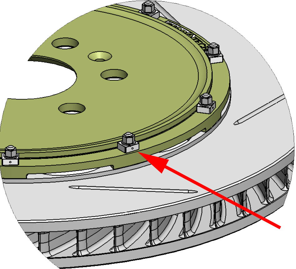
IMPORTANT! Wedge lock drive pins are directional, with proper orientation indicated by a machined depression on the upper portion. For LEFT side rotor assemblies, the machined dimple must face outward, as shown below:
LEFT SIDE ROTOR ASSEMBLY
For RIGHT side rotor assemblies, the machined dimple must face toward the center of the rotor, 180 degrees opposite the LEFT side assembly. Failure to orient the drive pins properly may result in accelerated pin wear, hat wear, and reduced effectiveness at controlling unwanted ABS behavior.
To install, place the lower half of a drive pin through the hat and rotor mounting hole. Place a washer onto the bolt and insert the bolt from the rotor side, through the drive pin. Install the upper drive pin half and orient the depression poperly (facing out for a LEFT rotor assembly, facing in for a RIGHT rotor assembly). Install the nut on the end of the bolt and tighten to 7.1-8.1 Newton Meters (63 inch pounds - 72 inch pounds). No thread locking compound is required.
- 2 x Ferodo DS1.11 Endurance race pads - front (D946) [1 box required]
- 2 x 28mm Caliper Rebuild Kit - 2 Dust Boots & Pressure Seals for 28mm pistons
- 1 x Ferodo DS1.11 Endurance race pads - front (D1792) [1 box required]
- 2 x Hawk DTC-70 race pads - rear (D345/D446/D608) [1 box required]
- 1 x PFC08 race pads - race caliper (CP3558-D54) 25mm thick, includes center eyelet
- 2 x Hawk DTC-70 race pads - rear (D31/D58/D861) [1 box required]
- 1 x Porterfield R4 race pads - front (D1977) (Special order) [1 box required] 14.6mm thick
- 1 x Ferodo DS1.11 Endurance race pads - front (DR770-20) 20mm thick [1 box required] BACKORDERED
- 1 x Caliper rebuild kit - front (38/42mm pistons) to rebuild one 4-piston caliper UNAVAILABLE
- 2 x Porterfield R4 race pads - front (D621) (Special order) [1 box required]
- 3 x Porterfield R4 race pads - rear (D345/D608) (Special order) [1 box required]
- 1 x Porterfield R4-S high performance street pads - front (D1166) (Special order) [1 box required]
- 1 x Ferodo DS2500 race pads - front (D810/D968) [1 box required] sensor slot, 18mm thick
- 2 x Porterfield R4 race pads - front (D1007) (Special order) [1 box required]
- 1 x Hawk HP Plus brake pads - rear (D810/D968/D1383) [1 box required] 17mm thick
- 1 x Porterfield R4 race pads - front (D1009) (Special order) [1 box required]
- 1 x Hawk Performance Ceramic brake pads - front (D639) [1 box required] 15mm thick BACKORDERED
- 1 x Ferodo DS1.11 Endurance race pads - front (D918) [1 box required] BACKORDERED
- 1 x Porterfield R4 race pads - front (D372/D447/D609) (Special order) [1 box required] 17.1mm thick
- 1 x Ferodo DS1.11 Endurance race pads - rear (D1718/D1854) [1 box required]
- 1 x Porterfield R4 race pads - front (D394) (Special order) [1 box required]
- 1 x Porterfield R4 race pads - front (D1634) (Special order) [1 box required] 17mm thick
- 1 x Brake pad wear sensor for BMW - Front
- 1 x Posi Quiet semi-metallic brake pads - rear (D31) [1 box required]
- 1 x Brake pad wear sensor for BMW - Front
- 1 x Hawk HPS 5.0 brake pads - rear (D810/D968/D1383) [1 box required] no sensor slot, 17mm thick
- 1 x Porterfield R4 race pads - front (D592/D1053) (Special order) [1 box required]
- 1 x Posi Quiet Ceramic brake pads - rear (D810/D968) [1 box required]
- 1 x 32mm Caliper Rebuild Kit - 2 Dust Boots & Pressure Seals for 32mm pistons
- 1 x StopTech Racing STR660 brake fluid - 622 F dry, 404 F wet boiling point (1/2 liter)
- 2 x Hawk Performance Ceramic brake pads - rear (D592/D1053) [1 box required] 14.5mm thick
- 1 x Porterfield R4 race pads - front (D1322) (Special order) [1 box required]
- 1 x Ferodo DS1.11 Endurance race pads - front (D394) [1 box required]
- 1 x Brake pad wear sensor for Audi/Porsche/VW - Front
- 1 x Ferodo DS1.11 Endurance race pads - front (D1741) [1 box required]
- 1 x Brake pad wear sensor for Audi/Porsche/VW - Rear
- 1 x Brake pad wear sensor for Audi/Porsche/VW - Front
- 1 x Brake pad wear sensor for Audi/Porsche/VW - Front
- 1 x Brake pad wear sensor for Audi/Porsche/VW - Rear
- 1 x Brake pad wear sensor for Audi/Porsche/VW - Rear
- 1 x Posi Quiet Ceramic brake pads - front (D561) [1 box required] 16.8mm thick
- 1 x PFC01 race pads - race caliper (DR17) 28mm thick, 62mm radial pad depth [1 box required]
- 1 x Hawk HP Plus brake pads - rear (D592/D1053) [1 box required] 14.5mm thick
- 3 x Ferodo DS1.11 Endurance race pads - rear (D345/D608) [1 box required] 18mm thick
- 2 x Ferodo DS3000 race pads - rear (D810/D968) [1 box required]
- 1 x PFC08 race pads - race caliper (D1247) [1 box required] 17mm thick, no center eyelet LIMITED QUANTITIES
- 3 x Hawk HPS brake pads - rear (D345/D446/D608) [1 box required]
- 1 x PFC11 race pads - front race caliper (7968) [1 box required] 28mm thick
- 1 x Brake pad wear sensor for BMW - Front
- 1 x Stainless lines - Rear
- 1 x Porterfield R4 race pads - front (D503) (Special order) [1 box required]
- 1 x Brake pad wear sensor for Audi/Porsche/VW - Front
- 1 x Brake pad wear sensor for BMW - Front
- 1 x Ferodo DS1.11 Endurance race pads - Brembo 6-piston monobloc caliper (wide annulus - 57mm)
- 1 x Porterfield R4 race pads - front (D1291) (Special order) [1 box required]
- 1 x Brake pad wear sensor for BMW - Front
- 1 x Hawk HPS brake pads - front (D345/D446/D608) [1 box required]
- 2 x Hawk HPS brake pads - front (D592/D1053) [1 box required] 14.5mm thick
- 1 x Motul RBF 660 racing brake fluid (Case of 12 bottles) - 617 F dry, 401 F wet boiling point (1/2 liter)
- 2 x PFC11 race pads - front (D592/D1053) [1 box required] 15mm thick
- 2 x Ferodo DS2500 race pads - front (D82) [1 box required] BACKORDERED
- 1 x PFC08 race pads - rear (D1299/D1300) [1 box required]
- 1 x Ferodo DS1.11 Endurance race pads - front (D1598) [1 box required]
- 1 x Porterfield R4 race pads - Brembo 6-piston monobloc caliper (57mm radial pad depth) (Special Order) [1 box required]
- 1 x 38mm Caliper Rebuild Kit - 2 Dust Boots & Pressure Seals for 38mm pistons (4 in stock)
- 1 x Hawk Performance Ceramic brake pads - front (D592/D1053) [1 box required]14.5mm thick
- 3 x Porterfield R4-S high performance street pads - rear (D1166) (Special order) [1 box required] 14mm thick, accomodates sensor
- 1 x PFC08 race pads - rear (D372/D609) [1 box required] 17mm thick
- 1 x Hawk HPS brake pads - rear (D592/D1053) [1 box required] 14.5mm thick
- 1 x Brake pad wear sensor for BMW
- 1 x Porterfield R4 race pads - front (D598) (Special order) [1 box required]
- 1 x PFC11 race pads - OEM Brembo (D592/D1053) [1 box required] 15mm thick
- 1 x Ferodo DS1.11 Endurance race pads - rear (D683) [1 box required]
- 1 x Ferodo DS1.11 Endurance race pads - rear (D396) [1 box required]
- 1 x Brake pad wear sensor for Audi/Porsche/VW - Front
- 1 x Porterfield R4 race pads - front (D1801) (Special order) [1 box required]
- 1 x Porterfield R4 race pads - front (D530) (Special order) [1 box required]
- 1 x Ferodo DS1.11 Endurance race pads - rear (D810/D968) [1 box required] sensor slot, 18mm thick
- 1 x PFC11 race pads - front (D345/D608) [1 box required]
- 1 x Motul RBF 600 racing brake fluid (Case of 12 bottles) - 594 F dry, 401 F wet boiling point (1/2 liter)
- 1 x Brake pad wear sensor for Audi/Porsche/VW - Front
- 2 x StopTech Sport 309-series brake pads - rear (D345/D608) [1 box required] 17mm thick
- 1 x PFC11 race pads - front (D558) [1 box required]
- 1 x Brake pad wear sensor for Audi/Porsche/VW - Front
- 1 x Ferodo DS1.11 Endurance race pads - rear (D592/D1053) [1 box required] 15mm thick
- 1 x Ferodo DS2500 race pads - for AP Racing calipers (CP2270-D50, CP2271) [1 box required]
- 1 x Brake pad wear sensor for BMW - Front
- 1 x Porterfield R4 race pads - front (D345/D608) (Special order) [1 box required]
- 1 x Porterfield R4 race pads - front (D829) (Special order) [1 box required] no sensor
- 2 x Stainless lines - Front
- 1 x Ferodo DS2500 race pads - front (D1001-1) [1 box required] 16mm thick, no sensor or damping weights
- 1 x Brake pad wear sensor for Audi/Porsche/VW - Rear
- 1 x Ferodo DS1.11 Endurance race pads - front (D1609) [1 box required] 18mm thick
- 1 x Hawk DTC-60 race pads - rear (D592/D1053) [1 box required] 14.5mm thick
- 1 x PFC01 race pads - race caliper (CP7600-D46) [1 box required] 16mm thick
- 1 x PFC11 race pads - rear (D592/D1053) [1 box required] 15mm thick
- 1 x PFC08 race pads - front (D918) [1 box required]
- 2 x StopTech Sport 309-Series brake pads - front (D345/D608) [1 box required] 17mm thick
- 1 x Hawk HPS 5.0 brake pads - rear (D592/D1053) [1 box required] 14.5mm thick
- 1 x PFC Z-Rated high performance brake pads - StopTech ST-60 caliper (D1247) [1 box required]
- 1 x Porterfield R4 race pads - front (D629) (Special order) [1 box required]
- 1 x Ferodo DS1.11 Endurance race pads - rear (D1598) [1 box required]
- 1 x Brake pad wear sensor for Audi/Porsche/VW - Rear
- 1 x Porterfield R4 race pads - front (D682) (Special order) [1 box required]
- 1 x Ferodo DS1.11 Endurance race pads - front (D1001-1) [1 box required] 16mm thick, no sensor or damping weights
- 1 x Ferodo DS1.11 Endurance race pads - race caliper (CP3215D-50) [1 box required] 16.6mm thick
- 1 x Brake pad wear sensor for Audi/Porsche/VW - Front
- 1 x Brake pad wear sensor for BMW - Front
- 1 x Ferodo DS1.11 Endurance race pads - race caliper (CP2340-D43) [1 box required] 16mm thick
- 1 x Porterfield R4 race pads - front (D1081) (Special order) [1 box required]
- 1 x Porterfield R4 race pads - front (D1116) (Special order) [1 box required]
- 1 x Porterfield R4 race pads - front (D174) (Special order) [1 box required]
- 1 x Brake pad wear sensor for BMW - Front
- 1 x Porterfield R4 race pads - front (D32) (Special order) [1 box required]
- 1 x Brake pad wear sensor for BMW - Front
- 1 x Ferodo DS1.11 Endurance race pads - rear (D1761) [1 box required]
- 1 x Porterfield R4 race pads - front (D373) (Special order) [1 box required]
- 1 x Brake pad wear sensor for BMW - Front
- 1 x Porterfield R4 race pads - front (D137) (Special order) [1 box required]
- 2 x PFC Carbon Metallic brake pads - rear (D989) [1 box required]
- 2 x Brake pad wear sensor for BMW - Front
- 2 x Porterfield R4 race pads - front (D822) (Special order) [1 box required]
- 1 x Ferodo DS1.11 Endurance race pads - front (D810/D968) [1 box required] sensor slot, 18mm thick
- 2 x Porterfield R4 race pads - front (D163) (Special order) [1 box required]
- 1 x Ferodo DS1.11 Endurance race pads - front (D1395) [1 box required]
- 1 x Hawk HPS 5.0 brake pads - rear (D345/D446/D608) [1 box required] 16.5mm thick
- 1 x Porterfield R4 race pads - front (D1835) (Special order) [1 box required]
- 1 x Brake pad wear sensor for Audi/Porsche/VW - Front
- 1 x StopTech Sport 309-Series brake pads - rear (D1053) [1 box required] 14.6mm thick
- 1 x Porterfield R4 race pads - front (D409) (Special order) [1 box required]
- 1 x Posi Quiet Ceramic brake pads - rear (D1053) [1 box required] 14.6mm thick
- 1 x Brake pad wear sensor for Audi/Porsche/VW - Rear
- 1 x Porterfield R4 race pads - front (D422) (Special order) [1 box required]
- 1 x PFC08 race pads - rear (D279) [1 box required]
- 1 x Hawk HP Plus brake pads - front (D960) [1 box required] 14.5mm thick
- 1 x 32mm diameter StopTech caliper piston - 29.5mm length UNAVAILABLE
- 1 x Porterfield R4 race pads - Brembo 6-piston monobloc caliper (49mm radial pad depth) (Special Order) [1 box required]
- 1 x Porterfield R4 race pads - front (D1448) (Special order) [1 box required]
- 1 x PFC11 race pads - front (D44) [1 box required]
- 2 x Ferodo DS2500 race pads - rear (D810/D968) [1 box required] sensor slot, 18mm thick
- 1 x Ferodo DS1.11 Endurance race pads - rear (D919) [1 box required]
- 1 x Porterfield R4 race pads - front (D31) (Special order) [1 box required]
- 1 x PFC11 race pads - front (D960) [1 box required]
- 1 x Brake pad wear sensor for BMW - Front
- 1 x PFC08 race pads - front (D991) [1 box required] 65mm radial depth, 17mm thick
- 1 x Porterfield R4 race pads - front (D507) (Special order) [1 box required]
- 1 x Posi Quiet semi-metallic brake pads - front (D1166) [1 box required] 14mm thick, accomodates sensor BACKORDERED
- 1 x Brake pad wear sensor for BMW - Front
- 1 x Porterfield R4 race pads - front (D1575) (Special order) [1 box required]
- 1 x Brake pad wear sensor for BMW - Front
- 2 x Posi Quiet Ceramic brake pads - rear (D108) [1 box required]
- 1 x Hawk HP Plus brake pads - front (D810/D968/D1383) [1 box required] 17mm thick
- 1 x Ferodo DS2500 race pads - rear (D592/D1053) [1 box required] 15mm thick
- 1 x Porterfield R4 race pads - front (D1365) (Special order) [1 box required]
- 1 x Porterfield R4 race pads - front (D582) (Special order) [1 box required]
- 1 x Ferodo DS1.11 Endurance race pads - rear (D732) [1 box required]
- 1 x StopTech Sport 309-series brake pads - front (D1053) [1 box required] 14.6mm thick
- 1 x PFC11 race pads - front (D1637) [1 box required]
- 1 x 34mm Caliper Rebuild Kit - 2 Dust Boots & Pressure Seals for 34mm pistons
- 1 x Brake pad wear sensor for Audi/Porsche/VW - Front
- 1 x PFC08 race pads - race caliper (DR40) [1 box required] 25mm thick, Radial Depth 52mm
- 1 x Porterfield R4 race pads - front (D273) (Special order) [1 box required]
- 1 x Ferodo DS1.11 Endurance race pads - race caliper (CP7040-D61) [1 box required] 16.9mm thick
- 1 x Brake pad wear sensor for BMW - Front
- 1 x Hawk DTC-70 race pads - front (D592/D1053) [1 box required] 14.5mm thick
- 1 x Hawk DTC-60 race pads - OEM Brembo (D345/D446/D608) [1 box required] 16.5mm thick
- 1 x StopTech Sport 309-Series brake pads - front (D45) [1 box required]
- 1 x Hawk DTC-70 race pads - rear (D592/D1053) [1 box required] 14.5mm thick
- 1 x Posi Quiet Ceramic brake pads - front (D345/D608) [1 box required]
- 1 x Porterfield R4 race pads - front (D229) (Special order) [1 box required]
- 1 x PFC Carbon Metallic brake pads - rear (D785) [1 box required]
- 1 x Hawk DTC-60 race pads - rear (D345/D446/D608) [1 box required]
- 1 x StopTech Sport 309-Series brake pads - front (D810/D968) [1 box required]
- 1 x Ferodo DS1.11 Endurance race pads - race caliper (CP7600-D46) [1 box required] 16mm thick
- 1 x Posi Quiet Ceramic brake pads - front (D810/D968) [1 box required]
- 1 x Ferodo DS1.11 Endurance race pads - race caliper (FRP3014) [1 box required] 54mm radial depth, 25mm thick, no center eyelet
- 1 x Hawk DTC-60 race pads - front (D810/D968/D1383) [1 box required] 17mm thick
- 1 x PFC11 race pads - front (D991M) [1 box required] 60mm radial depth, 17mm thick
- 1 x Hawk DTC-60 race pads - front (D960) [1 box required] 14.5mm thick
- 1 x Hawk Performance Ceramic brake pads - rear (D345/D446/D608) [1 box required]
- 1 x Porterfield R4 race pads - front (D294) (Special order) [1 box required]
- 1 x Ferodo DS2500 race pads - front (D561) [1 box required]
- 1 x Brake pad wear sensor for Audi/Porsche/VW - Front
- 1 x 36mm diameter StopTech caliper piston - 32mm length (23 in stock)
- 1 x Ferodo DS1.11 Endurance race pads - OEM Brembo (D810/D968) [1 box required] sensor slot, 18mm thick
- 1 x PFC Carbon Metallic brake pads - front (D784) [1 box required]
- 1 x Brake pad wear sensor for Audi/Porsche/VW - Front
- 1 x Porterfield R4 race pads - front (D484) (Special order) [1 box required]
- 1 x Brake pad wear sensor for Audi/Porsche/VW - Rear
- 1 x PFC08 race pads - front (D776/D917/D993/D1135) [1 box required] - Does not accomodate wear sensors
- 1 x Pagid RSL29 Yellow Endurance Race Pads - front (D253/D395) [1 box required]
- 1 x PFC Carbon Metallic brake pads - front (D727) [1 box required]
- 1 x PFC08 race pads - rear (D1001) [1 box required] 15mm thick, no sensor or damping weights
- 1 x 1-Piece 355x32mm AeroRotor Slotted, Right (Fits Saleen, Roush Mustang. Also fits StopTech 82-330-4700, 82-330-6700 big brake kits)
- 1 x Bleed Screw for rear brake calipers - M7x1.0mm, sold individually (8 in stock)
- 1 x Ferodo DS1.11 Endurance race pads - rear (D174/D961) [1 box required]
- 1 x Ferodo DS2500 race pads - front (D253/D395) [1 box required]
- 1 x Porterfield R4 race pads - front (D722) (Special order) [1 box required]
- 1 x Porterfield R4 race pads - front (D310) (Special order) [1 box required]
- 1 x Porterfield R4 race pads - front (D45) (Special order) [1 box required]
- 1 x Porterfield R4 race pads - front (D278) (Special order) [1 box required]
- 1 x Porterfield R4 race pads - front (D1730) (Special order) [1 box required]
- 1 x Hawk HP Plus brake pads - rear (D345/D446/D608) [1 box required]
- 1 x PFC11 race pads - front (D45) [1 box required]
- 1 x Brake pad wear sensor for Audi/Porsche/VW - Front
- 1 x Porterfield R4 race pads - front (D431) (Special order) [1 box required]
- 2 x Hawk HPS 5.0 brake pads - front (D810/D968/D1383) [1 box required] 17mm thick
- 1 x Porterfield R4 race pads - front (D590) (Special order) [1 box required] 19mm thick, no sensor
- 1 x StopTech Sport 309-series brake pads - rear (D810/D968) [1 box required]
- 1 x Porterfield R4 race pads - front (D1784) (Special order) [1 box required]
- 1 x Porterfield R4 race pads - front (D506) (Special order) [1 box required]
- 1 x Porterfield R4 race pads - front (D702) (Special order) [1 box required]
- 1 x Ferodo DS1.11 Endurance race pads - rear (D1599) [1 box required]
- 1 x Brake pad wear sensor for Audi/Porsche/VW - Front
- 1 x PFC08 race pads - front (D345/D608) [1 box required]
- 1 x Brake pad wear sensor for Audi/Porsche/VW - Front
- 1 x Hawk HP Plus brake pads - front (D592/D1053) [1 box required] 14.5mm thick
- 1 x Brake pad wear sensor for BMW - Front
- 1 x Brake pad wear sensor for Audi/Porsche/VW - Front
- 1 x Ferodo DS1.11 Endurance race pads - rear (D1001) [1 box required] 14.7mm thick, no sensor slot or damping weights
- 1 x Porterfield R4 race pads - front (D1633) (Special order) [1 box required]
- 1 x PFC Z-Rated high performance brake pads - StopTech ST-40 caliper (D372/609) [1 box required] 17mm thick
- 1 x 28mm diameter StopTech caliper piston - 29.5mm length (42 in stock)
- 1 x Porterfield R4 race pads - front (D565) (Special order) [1 box required]
- 1 x Ferodo DS2500 race pads - for AP Racing calipers (CP2399-D43) [1 box required]
- 1 x PFC01 race pads - race caliper (CP3558-D54) [1 box required] 25mm thick, includes center eyelet
- 1 x Ferodo DS1.11 Endurance race pads - Brembo 6-piston monobloc caliper (narrow annulus - 49mm)
- 1 x Ferodo DS1.11 Endurance race pads - front (D1609-1) [1 box required] 15mm thick (BACKORDERED)
- 1 x Brake pad wear sensor for Audi/Porsche/VW - Rear
- 3 x Posi Quiet Ceramic brake pads - rear (D345/D608) [1 box required]
- 1 x Brake pad wear sensor for Audi/Porsche/VW - Front
- 1 x Porterfield R4 race pads - front (D561) (Special order) [1 box required]
- 1 x Ferodo DS1.11 Endurance race pads - front (D1029) [2 boxes required] 4 pad set, no sensor
- 1 x Ferodo DS1.11 Endurance race pads - rear (D372/D609) [1 box required] 18mm thick
- 1 x Porterfield R4 race pads - front (D138/D154/D202) (Special order) [1 box required]
- 1 x Brake pad wear sensor for Audi/Porsche/VW - Rear
- 1 x Ferodo DS1.11 Endurance race pads - front (D592/D1053) [1 box required] 15mm thick
- 1 x PFC11 race pads - rear (D31) [1 box required]
- 1 x Brake pad wear sensor for BMW - Front
- 1 x Stainless lines - Rear (Also fits StopTech BBK 83-305-0046) UNAVAILABLE
- 1 x Ferodo DS1.11 Endurance race pads - front (D372/D609) [1 box required] 18mm thick
$62,142.94